Anechoic and Semi-Anechoic Chambers: Differences and Applications
An anechoic chamber and a semi-anechoic chamber are environments used to perform electromagnetic measurements under controlled conditions. Both can be designed to limit external interference and reduce electromagnetic wave reflections, but their construction differs, determining their suitability for different applications.
The choice between the two types depends on the test to be performed, the characteristics of the device under test, and the requirements specified by the applicable measurement procedure or standard.
What is an anechoic chamber?
An RF anechoic chamber is an environment designed to reduce electromagnetic wave reflections from internal surfaces and enable measurements under controlled conditions.
The structure generally consists of a shielded enclosure and absorbing materials installed on its internal surfaces. These two elements perform different functions:
- Electromagnetic shielding: limits the coupling of signals from the external environment and helps contain emissions generated inside the chamber.
- Absorbing materials: attenuate electromagnetic waves reflected by the walls, ceiling and, in fully anechoic chambers, the floor.
The goal is to create a measurement region with controlled electromagnetic characteristics, where reflections do not significantly compromise the results.
This region is often referred to as the quiet zone. Its dimensions and characteristics depend on the chamber geometry, the arrangement of the absorbers, the frequency and the test configuration.
To learn more about construction principles and the materials used, read our guide to the anechoic chamber for RF and microwave testing.
What is a semi-anechoic chamber?
A semi-anechoic chamber, often referred to as an SAC (Semi-Anechoic Chamber), is a shielded environment in which the walls and ceiling are lined with absorbing materials, while the test floor consists of a reflective conductive surface.
This configuration makes it possible to control reflections from the sides and above while retaining the reflective contribution of the ground plane.
The conductive ground plane is an important element in many EMC tests because it helps establish defined measurement conditions and ensures that results obtained according to a specific procedure can be compared.
Semi-anechoic chambers are commonly used for radiated emission tests and can also be used for radiated immunity tests when permitted by the applicable test procedure.
Anechoic vs. semi-anechoic chambers: what are the differences?
The main structural difference concerns the treatment of the floor: in a fully anechoic chamber, this surface is also covered with absorbing material, whereas in a semi-anechoic chamber, the test floor remains conductive and reflective.
| Feature | Fully anechoic chamber | Semi-anechoic chamber |
|---|---|---|
| Walls | Absorbing materials | Absorbing materials |
| Ceiling | Absorbing materials | Absorbing materials |
| Floor | Absorbing material | Reflective conductive ground plane |
| Propagation conditions | Reduced reflections from all internal surfaces | Reduced reflections from absorbing surfaces, with the contribution of the ground plane |
| Typical applications | Antenna characterization, measurements under free-space-like conditions and specific EMC tests | EMC radiated emission and immunity tests, depending on the required configuration |
These two solutions are not interchangeable in every situation. The choice depends on the device under test, the required configuration and the applicable test standard.
Which EMC tests are performed in anechoic and semi-anechoic chambers?
EMC (Electromagnetic Compatibility) tests evaluate the electromagnetic emissions of a device and its ability to operate correctly in the presence of disturbances.
The main types of tests are described below.
Radiated emission tests
Radiated emission tests measure the electromagnetic disturbances generated by the device under test and radiated into the surrounding space.
During the test, the device is placed in a defined configuration, and its emissions are detected using antennas and measurement equipment. The antenna position, distance, device orientation and environmental conditions must be consistent with the applicable test method.
Semi-anechoic chambers are widely used for these measurements because they provide a controlled test environment while retaining the ground plane required by many EMC procedures.
Radiated immunity tests
Radiated immunity tests evaluate how a device responds when exposed to an intentionally generated electromagnetic field.
In this case, the test system includes an RF source, an amplifier when necessary, a transmitting antenna and equipment for controlling the applied field.
It is essential that the field in the region occupied by the device meets the requirements specified by the test procedure. Uncontrolled reflections can alter the field distribution and affect the test results.
Anechoic and semi-anechoic chambers can be used for these applications, provided that their geometry, frequency range, configuration and field verification are compatible with the applicable procedure.
Antenna radiation pattern characterization
When the objective is to characterize an antenna's radiation pattern, reflections that could interfere with measurements of the radiated field must be limited.
A fully anechoic chamber is particularly suitable for measurements requiring free-space-like propagation conditions, provided that the chamber characteristics are appropriate for the frequency and dimensions of the antenna under test.
These measurements make it possible to study the angular distribution of the radiated field and characterize the antenna's behaviour under the specified operating conditions.
Why are absorbing materials important?
Electromagnetic absorbers reduce the energy of waves reflected from the chamber's internal surfaces. Their selection depends on the frequency range, the required attenuation level and the characteristics of the measurement.
The solutions used include:
- Ferrite absorbers, used in configurations designed to operate at lower frequencies than those that can be handled using pyramidal absorbers alone.
- Pyramidal absorbers, made from materials and geometries designed to attenuate incident waves over a specific frequency range.
The shape, height and arrangement of the absorbers affect the overall performance of the chamber. The internal geometry, the dimensions of the measurement region and the position of the device also help determine the electromagnetic conditions that can actually be achieved.
For this reason, the presence of absorbing materials alone does not automatically guarantee that a chamber is suitable for every type of test.
How can you verify whether a chamber is suitable for EMC measurements?
To obtain reliable and repeatable results, the chamber and the test configuration must be verified according to the applicable method.
Depending on the intended application, verification may cover different aspects:
- Test site performance: evaluation of the electromagnetic characteristics of the environment and its suitability for the specific measurement method.
- Field uniformity: verification of the field distribution within the test region, when required by the procedure.
- Shielding performance: measurement of the attenuation of signals passing through the shielded enclosure.
- Measurement equipment suitability: verification of the characteristics of the antennas and other instruments used for the measurement.
The IEC CISPR 16-1-4 standard addresses the characteristics and performance of antennas and test sites used for radiated disturbance measurements. Its applicability and the methods to be used must be assessed according to the type of test and the relevant product standard.
For more information about test site verification, see the MPB guide to CISPR 16-1-4 and EMC site validation.
It is also important to distinguish test site validation from shielding effectiveness verification: these are different activities with specific objectives and measurement procedures.
Anechoic chamber and Faraday cage: are they the same thing?
No. A Faraday cage is a conductive enclosure designed to attenuate electromagnetic coupling through its surface. An RF anechoic chamber also uses absorbing materials to control internal reflections.
A shielded anechoic chamber therefore combines two functions: electromagnetic isolation from the external environment and the reduction of reflections inside the chamber.
Good shielding performance does not, by itself, guarantee anechoic conditions. Similarly, absorbers cannot replace the continuity and performance required of the shielded enclosure.
To learn more about this topic, read the MPB article on the Faraday cage and our guide to shielding effectiveness.
MPB's RF anechoic chamber
At MPB's laboratory, the anechoic chamber described in our technical guide measures 6 × 4 metres and covers a measurement frequency range from 200 MHz to 40 GHz.
It is used to characterize antenna radiation patterns, perform calibration of electric and magnetic field sensors, and support research and development activities during the design of new measurement instruments.
The chamber's characteristics and the adopted configuration are considered according to the application and the specific measurement requirements.
For more information about the activities and applications of the RF anechoic chamber, contact MPB.
Frequently asked questions
What is the main difference between an anechoic and a semi-anechoic chamber?
The main structural difference is the floor: in a fully anechoic chamber, it is covered with absorbing material, whereas in a semi-anechoic chamber, it consists of a reflective conductive ground plane.
Which type of chamber is used for EMC testing?
It depends on the test. Semi-anechoic chambers are commonly used for radiated emission measurements and can also be used for radiated immunity tests. Fully anechoic chambers are suitable for applications requiring reduced reflections from all internal surfaces. The final choice depends on the applicable standard and test configuration.
Does an anechoic chamber eliminate all reflections?
No. The objective is to reduce reflections within the limits established by the chamber design and the operating frequency range. Performance depends on the absorbers, chamber geometry and measurement configuration.
Why does an anechoic chamber need to be verified?
Verification ensures that the test environment is suitable for the intended application and that measurement conditions meet the applicable requirements. Depending on the relevant procedures, checks may cover the test site, the field within the test region, shielding performance and measurement equipment.
Recent
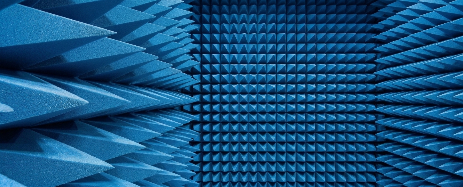
Anechoic and Semi-Anechoic Chambers: Differences and Applications
An anechoic chamber and a semi...
MPB at the AIRP National Conference 2026
MPB Srl will participate in th...
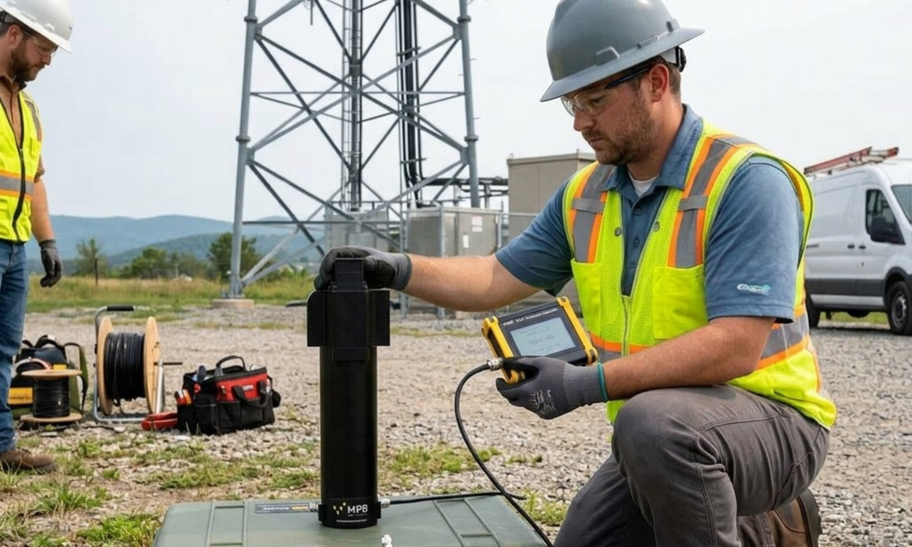
1. IntroductionThe validity of...

The importance of a fully non-magnetic tripod in Shielding Effectiveness (SE) measurements
In Shielding Effectiveness (SE...

ISO 17025 and accredited calibration: what it really means in the context of electromagnetic fields
In the field of electromagneti...
Contacts
MPB S.r.l.
Via Giacomo Peroni 400/402
Polo Tecnologico Tiburtino
00131 Roma RM
- Phone:
- +390641200744
- Fax:
- +390641200653
- E-mail:
- info@mpbelectronic.com


